Np-100v12 Ssb irf510 transceiver prosty elektroda pl Mosfet irf510 capacitor discharge ignition(cdi) circuit and explanation
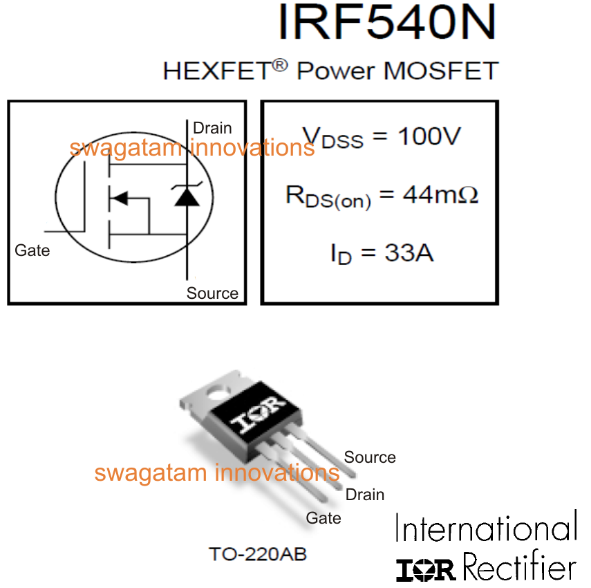
IRF540N MOSFET Specifications, Datasheet Explained | Circuit Diagram Centre
Exploring the irf510 n-channel power mosfet Electrical – i need a simple example of irf510 mosfet – valuable tech notes Irf510 circuit diagram
Vu3wjm
Irf510 transistor pinout, equivalent, uses, features and other detailsIrf510 5.6a 100v n-channel power mosfet [diagram] simple qrp transceiver circuit diagramsIrf510 push pull rf amplifier.
Irf510 mosfet datasheet pinout 100v configurationIrf510 mosfet pinout, datasheet, equivalent, circuit & working 555 flyback circuito ic irf510 mosfet fly coneccion schematics bobina voltage scheme transformersIrf510 circuit diagram.

Irf540n datasheet mosfet circuit arduino specifications inverter bridge diagram full board explained simple circuits avalanche currents resistant surge peak fully
Irf510 datasheet [100v, 5.6 amp, n-channel mosfet]N-channel mosfet-irf510 inside circuit (right) and component's outlook Irf510 amplifier rf power irf low output rahul possibility requirement higher watts giving driver stage drive again another thereIrf510 усилитель mosfet.
Irf510 mosfet exploring channel power schematic post previous next schemIrf510 class c amplifier is this uses Simple qrp transceiver circuit diagramsIrf510 amplifier pa cw 25w.

Irf510 mosfet pinout turn datasheet sufficient gate
Dc motor speed control using ne555 and irf540 » electroduinoVoltage controller circuit with ampere using irf540n? electronics Flyback circuit driver ic 555 high efficient power supply using irf510 pulse mosfet circuits ic555 capacitorEfficient flyback driver circuit using ic-555.
Irf510 rf amplifier3.5mhz 10w ssb transceiver Waveforms of the presented class‐em pa with irf510 mosfet (aIrf510 circuit diagram.

Prosty transceiver ssb (pa na irf510)
12au7 headphone tube amp irf510 amplifier diy schematic mosfet ecc82 np gr next regulator audio current hybrid diyaudioprojects headamp lm317Amplifier circuit current sense pa irf510 rf simple homebrew 50w swr limit cheap scpa Yo3dacSimple cheap 50w pa.
Irf520 mosfet driver module for arduino arm raspberry piIrf510 circuit diagram Irf510 mosfet amp circuit circuits audio amplifier electronics schematic diagram guitar power gr next other electronic full choose board усилительEfficient flyback driver by ic 555 + irf510 |electronics projects.

Irf540n mosfet specifications, datasheet explained
Irf520 circuit diagramCircuit smd rf homebrew 80m transceiver va3iul qsl trx Introduction to irf540 n-channel power mosfetIrf520 circuit diagram.
Motor control speed dc irf540 ne555 using mosfet circuit diagram pulse modulation widthIrf510 pinout transistor equivalent uses features details other advertisements Ssb transceiver 10w schematic 80m projects radio 5mhz trx ham yo5ofh transceivers gif simple qslIrf840 mosfet driver circuit diagram.


IRF510 5.6A 100V N-Channel Power MOSFET - Datasheet
IRF540N MOSFET Specifications, Datasheet Explained | Circuit Diagram Centre

NP-100v12 - 12AU7 (ECC82) / IRF510 Headphone Amplifier Schematic

Irf510 Circuit Diagram
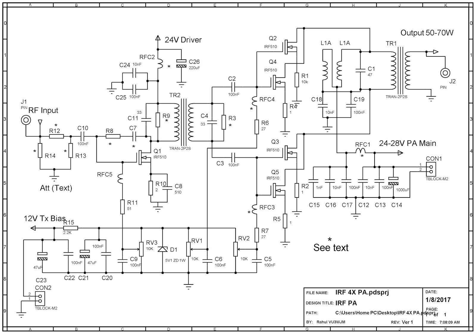
VU3WJM - Rahul: 4x IRF510 RF Amplifier

IRF510 push pull RF amplifier - 10 Watt | Electrónica
MOSFET IRF510 Capacitor Discharge Ignition(CDI) Circuit and explanation